Fuselage, Final Brake and Fuel Lines,
and Panel Part 2
Posted 2/8/2015
This update brings completion to a few things, and a temporary
end to any major construction items. We're *still* waiting
for the finishing kit to be released, so as we wait I'm going to
be keeping busy with non-airframe tasks. If we get into
late spring, I'll end up just painting the thing while I wait,
but hopefully it won't take that long.
 |
 |
 |
 |
| At this point all
of the pushrod controls are completed and most installed
except for the long elevator control going through the
tail, and the short aileron pushrods to the wings that are
obviously going to be part of the finishing kit because we
don't yet have them. What's suprised me is that there are
some things left out of the fuselage kit that you'd think
of as fuselage items...like the aileron pushrods, the seat
bottoms and backs, and tunnel and access port
covers. So none of that is available to be installed
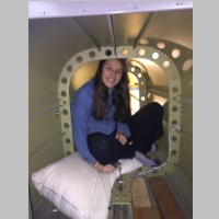
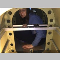
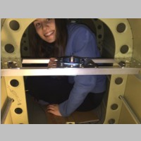
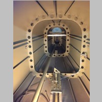
at this time. Just like as was done in the RV-10, I put my magnetometer in the tail, so I had to build a small shelf for that. This was one of the short mini-projects that I got some good help from my short mini-pilot with. I actually spent some time back in the tail myself while I got it all drilled, but she was very helpful in getting it riveted in place. Below you can also see the intermediate elevator pushrod bellcranks. |
|||
 |
 |
 |
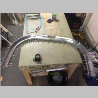 |
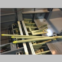
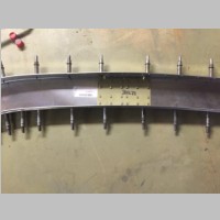
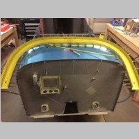
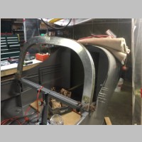
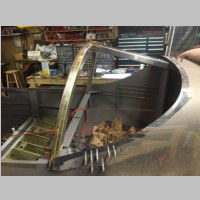
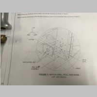
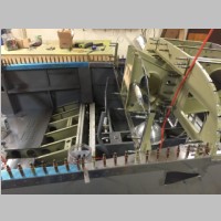
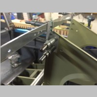
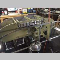
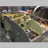
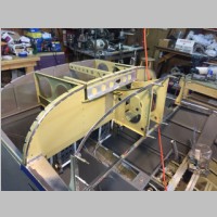
| After that work was
done, the only major parts left in the garage were related
to the roll bar protection. This was another short
day project, to get everything lined up, final drilled,
and then riveted. I continue to be amazed at how well
things fit. Once the roll bar was completed it
simply slid in place on the fuselage and could be
attached. |
|||
 |
 |
 |
 |
 |
 |
 |
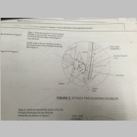 |
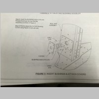
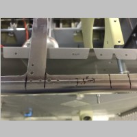
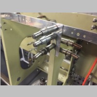
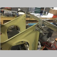
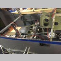
I did run into some plans confusion and got a half reply from Van's on the situation. There were only 10 LP4-5 rivets included in my hardware kit. On these plans pages you can see that there are 12 LP4-5 rivets used on the sides of the roll bars, and then an additional 4 per side at least on the front face. So you'd need 32 minimum I think. There were also 34 LP4-4 rivets included in the kit that appear NOWHERE in the plans. So, I tried to get it clarified if the parts were shorted or were we supposed to use LP4-4 rivets in some places because when you look at the various thicknesses, I really don't think LP4-5 rivets are the proper ones in some of the locations. The reply I got was that yes, hardware has been added to one of the bags. (Not that they were sending them to me, but that in the future they'd be added) And also that indeed in some places -4 or -5 length rivets could probably be used. That wasn't really the full clarity I was looking for, but I guess I can figure out the proper rivets to use on my own. It would be nice if they'd fully clarify that for people though. One thing that isn't on this page that was also recently completed were the final fuel lines from Aircraft Specialty. Their 5052-O fuel lines from valve to sidewall fit perfectly, and with those installed, all of the fuel and brake lines were ready for final torque. |
|||
 |
 |
 |
 |
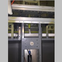
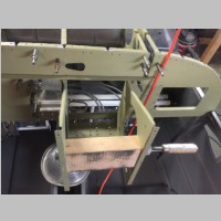
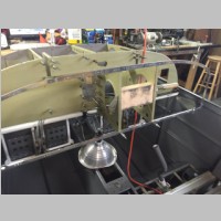
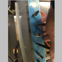
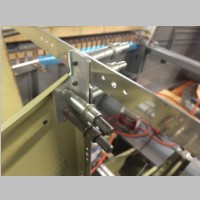
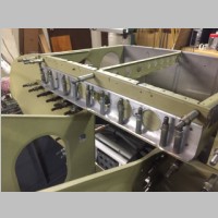
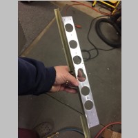
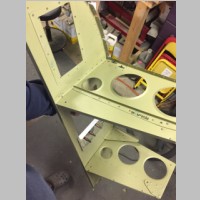
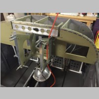
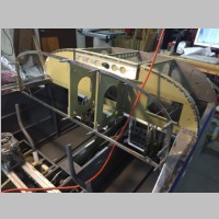
Now it was time to continue with the real fun stuff. As you may remember, I'm not much in favor of the lemming like "we'll do all the thinking and avionics picking for you" way that this kit was put together, so I have a lot of panel work to do. I moved the radio stack over 3.3" and prior to this work day I had the subpanel hole cut and ready to be reinforced. Today was the day it was time to actually cut the panel backing ring bars and move them over. I did find that Van's made a small error in the panel radio stack, as well. I thought it was just me until I talked to a panel supplier who said yes, the width is slightly too wide for the radio stack. Builders will have to shim the space on one side or the other of their avionics trays to take up the gap, or their radio install tubes will slightly bow outward making some of them not fit right for the radios. To be consistent front to rear, I cut a 2x4 block to the width of the rear of the radio stack ribs, and clamped it to the front. That set the width and allowed me to perfectly move the vertical bars over exactly 3.3 inches. |
|||
 |
 |
 |
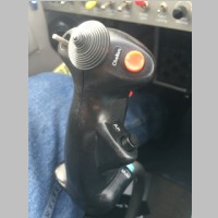 |
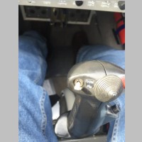
Here's a quick side note on the stick grips. It's going to be time to order my stick grips soon, so I took a photo in my RV10 to have current photos of the grips. The functions are: HAT switch = Trim Left Top Thumb = DPST - push up to flip-flop COM1, push down to swap intercom xmit COM1/COM2 Right Top Thumb = Red Button - Changes MFD display from MFD to Engine Monitor to PFD mode Trigger = Push to talk Right Thumb = Autopilot Disconnect / Control-wheel-steering Pinkie Button = EFIS Mute (shut off those annoying terrain alarms when needed) |
|||
 |
 |
 |
 |
 |
 |
 |
 |
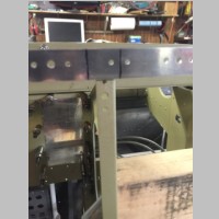
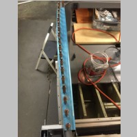
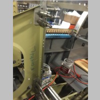
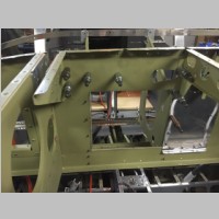
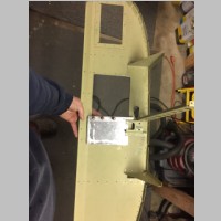
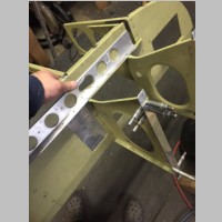
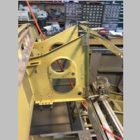
Before I could continue and finish installing the entire panel area, I had to quick finish the side deck surfaces where the canopy meets the fuselage. This involves sealing the gap with proseal and riveting in the covers to the longerons. I am thinking I'll fill at least the rivet holes, if not the rivets themselves, in this area for a finished look. Back to the panel ring, I had to now find a way to reattach the old vertical bars to the radio stack ribs, more as a shim than a strength adding feature. I cut some custom aluminum angle pieces to secure the frame at the top and bottom, and riveted those to the ribs. When all is done, the old vertical bars will just be large shims, and rather than installing a 3-piece panel as comes with the kit, I'm going to have SteinAir cut me a one piece panel. I will locate my own screw holes in those vertical bars to secure the panel, and add the nutplates for them later. This will be a little cleaner look than what is normal with the panel, and a single piece panel should add some strength and rigidity back to it as well. |
|||
 |
 |
 |
 |
 |
 |
 |
 |
 |
 |
 |
 |
 |
 |
 |
 |
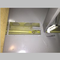
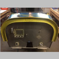
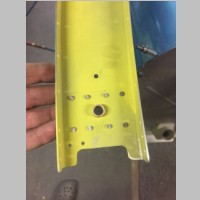
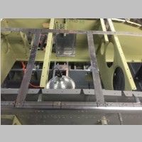
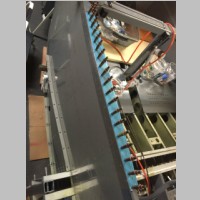
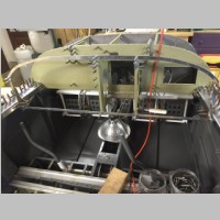
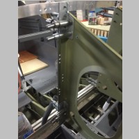
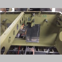
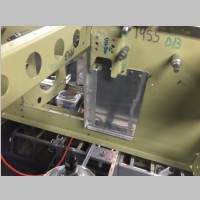
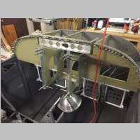
With the hole cut slightly higher for the radio stack in the sub panel, I had to chop into a horizontal angle strip that stiffened the sub panel. I'm sure I could have left it or used some thin stock to stiffen it, but I didn't want the subpanel to bow at all when the canopy was attached ,so I cut a custom piece of aluminum angle that would completely reinforce the area between the canopy hinges. As I riveted this whole assembly together, it was shocking how it went from being a bunch of flimsy parts to a very firm and sold structure. Once the top skin is installed, it will be very strong. it's probably strong enough now to lift the fuselage by, in fact! |
|||
 |
 |
 |
 |
 |
 |
 |
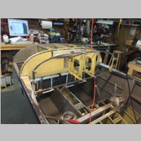 |
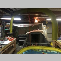
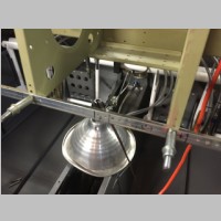
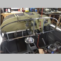
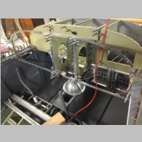
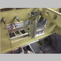
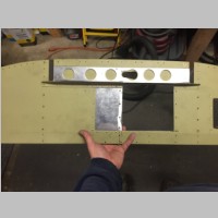
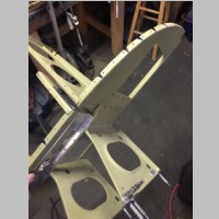
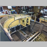
The rest of the pictures on this page are just progressive photos of the whole assembly during construction. At this point I'm now almost ready to have the panel cut and start fitting my avionics. I've ordered most of the items, and plan to start installing and wiring the panel as soon as all the items arrive. Luckily at SteinAir they have the ability to cut the panel on a CNC machine out of plexiglass as a test fit, so I intend to have a complete mock panel cut and test fit before the final aluminum panel is cut. This will ensure that all of the holes are in exactly the right places. |
|||
 |
 |
 |
 |