Firewall / Forward Fuselage / Mid-Fuselage
Posted 12/8/2014
First, start early, rather than later. If you have small kids, I understand your hesitation at wanting to start a project like this, but I can assure you of a few things. If you build it, your kids will enjoy flying in it, as long as you take them places. And, time only gets more scarce as they grow. It's far easier to take on a project like this when your kids are very young and not involved in as many activities. Both time and money become much tighter as you and they age. Waiting until they are teenagers will backfire. They will not have time to help, and your increasing lack of time will cause the build to slow down, and you risk not finishing it for them to even enjoy.
Next, hit the project hard and don't slow down. If you don't get out and work on it every day, you will find reasons NOT to work on it, and suddenly you will have progress that is so slow that it brings you down. If you keep at it every day, the project goes very quickly and the motivation stays high. The faster it comes together, the closer the reward becomes, and we are very much like dogs. With the fuselage coming together I am now salivating because Pavlov is making airplane noises in my ears.
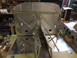
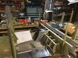
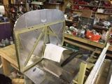
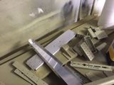
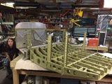
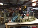
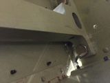
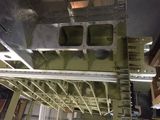
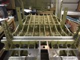
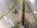
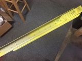
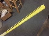
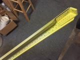
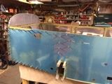
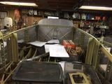
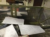
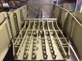
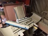
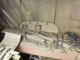
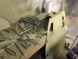
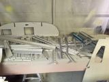
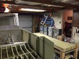
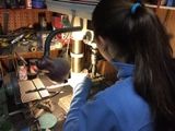
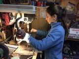
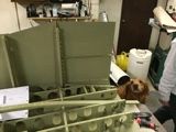
The section I'm currently working on is most of the structure of the fuselage. Here are some snippets that show the pre-construction stages.
 |
 |
 |
I have been finding the occasional plans error as I go through these sections. There are things that aren't quite as clear as the other kits, plus there are some things that need slight revisions from Van's. I won't even try to write about all of them, but in this section I'm going to add a couple of gotchas. I don't know if anyone even reads this drivel, but if it saves anyone from making mistakes, then it will be of benefit to someone.
 |
 |
 |
 |
||||||||||
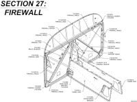
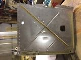
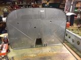
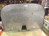
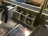
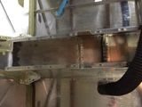
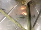
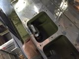
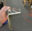
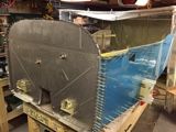
| The firewall on the RV-14 comes
in 4 pieces...more if you include the tunnel. It's
much different than what the RV-10 is designed like.
On the RV-10, the belly of the plane is all flat.
The tunnel in the center goes all the way to the belly of
the plane, giving lots of room. On the RV-14, there
is a cutout in the belly of the fuselage that is lined
with stainless steel, and the exhaust hangs in that center
area. This probably reduces drag, and perhaps gives
an increase in cowl exit area. I'm not sure on the exit
area thing though...depends on how the fiberglass cowl
fits into the picture. The sidewalls that your legs
touch, inside the cockpit, are not the direct walls around
the muffler, but there is an air gap between them. For those who aren't sure how much proseal to buy to build an RV-14, you'll need at least 2 cans, most likely, because you'll need it for the wings, and multiple places on the firewall, tunnel, and upper forward fuselage. |
|||||||||||||
 |
 |
 |
 |
||||||||||
 |
 |
 |
 |
||||||||||
 |
 |
 |
 |
||||||||||
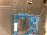
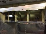
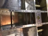
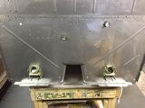
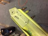
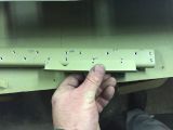
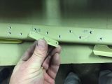
| One area that the plans have a
flaw, at least in the initial revision, is the battery
box. As you build the firewall, there are many
places to dimple and countersink, and many places you are
told not to dimple and countersink. Unfortunately,
the battery box holes were excluded from the "DO NOT
DIMPLE" and "DO NOT COUNTERSINK" callouts, which means
you'll be left with a firewall that is ready to have flush
rivets riveted on. The catch is, you need to rivet
the battery box on with flush rivets too. See the
last picture in the row below and you'll see the dimpled
holes where the battery box attaches. Make sure NOT
to dimple or countersink anything related to these holes. |
|||||||||||||
 |
 |
 |
 |
||||||||||
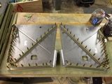
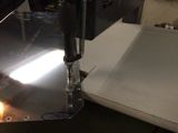
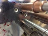
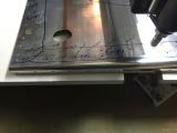
Now, since I was one of a few builders who had to work with the plans before any revisions, and I am building fairly quickly, I had to fix these dimples before attaching the battery box. There are two possibilities. You can either dimple the battery box, even though that aluminum is generally too thick for dimpling, or you can use countersink fillers. These are also called Countersink Repair Washers and are available many places, such as Gen-Aircraft-hardware.com. The part number I was looking at using was LS5931A71 (or even better, LS5931C71) These parts are basically just the upper rim of a countersunk rivet, designed to fill any countersunk hole where you may intend to either use a round head rivet, or place another repair layer of material over top. You want to ensure that the rivet shank, when you rivet it, will have material around it inside that void. The discouraging part about buying that piece is that they're not common enough to be cheap. They are, at the time of this writing, .558 cents each, with a 100 minimum, at the lowest cost I can get them. Some totally insane places think they can get $2.90/each in 100 minimums, or even $5.50 each in low quantities. Note to hardware sellers, we're not that dumb so don't try to screw everyone.
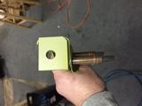
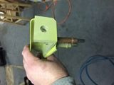
I started to think about it and realized that it wouldn't be THAT hard, if I were careful, to make these washers. I started with an AN426AD4-4 rivet, drilled the center with a #35-#36 drill, then used a #30 chucking reamer to carefully ream down into the head until the ring separated. A few of them I wasn't centered so I had to toss them. But I made enough to fill all 19 holes in the firewall. Above are some pictures of making them...my first one turned out great, but the 2nd wasn't quite centered. Anyway, it shows how they fit, and what a round rivet looks like over top that head, and even one with the round rivet put in from the other side so you can see how it fits real well. |
|||||||||||||
 |
 |
 |
 |
||||||||||
 |
 |
 |
 |
||||||||||
 |
 |
 |
 |
||||||||||
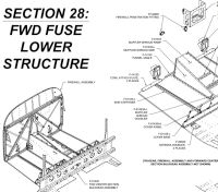
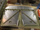
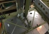
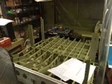
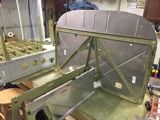
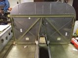
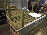
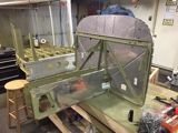
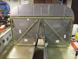
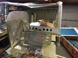
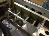
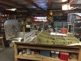
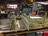
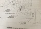
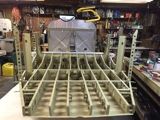
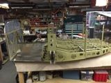
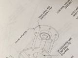
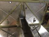
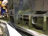
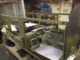
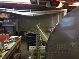
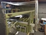
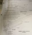
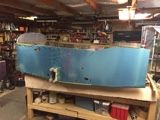
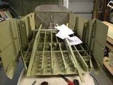
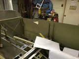
Before long, you have the foward firewall and floor completed and it's time to mate it with the mid-fuselage. This is where I was just shocked at how accurately these parts were engineered. Van's did a tremendous job making something so precise that you can take all of these multiple pieces and mate them up and everything just seems to line right up. It was really amazing. Below are some photos of the mated fuselage. There are a couple of notes on things to know before you proceed. 1) check the plans below. It talks of clocking the brass fitting to 3 degrees. The drawing says 6.9. The 6.9 is correct, although you'll never get it down to the .1 degree...you can see the intention is to route the brake line through a hole in the rib. 2) don't bother to fully torque the gear braces into the fuselage until you have the bottom skin fully riveted. You will find that you have to take it apart to reach the nutplates under the brace, and a few of the other rivets too...and no, you can't just rivet those first...you need the braces to ensure alignment. 3) Make sure to put the bolts in per-plans direction. For some, this would not be normal per standards, but, it is necessary if you ever want to be able to remove the bolts from a completed aircraft. Other than that it went together very simply. |
|||||||||||||
 |
 |
 |
 |
||||||||||
 |
 |
 |
 |
||||||||||
 |
 |
 |
 |
||||||||||
 |
 |
 |
 |
||||||||||
 |
 |
 |
 |
||||||||||
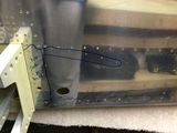
Above is another minor plans error I found. Obviously an AN470AD4 rivet is required for a #30 hole. One thing that had me a little perplexed for a few minutes is the orientation of the air vent cable brace. You will notice that the cable brace isn't a mirror image in how it mounts from side to side. This is because the vent door arm is the same for both sides, and the gap between the cable brace and the arm must be the key factor. So don't mount them as mirror images. Look under the Figure 2 label on page 28-10 and it says "Left Side Shown, Right Side identical - Not Mirrored". Took me a while to notice that. |
|||||||||||||
 |
 |
 |
 |
||||||||||
 |
 |
 |
 |
||||||||||
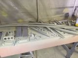
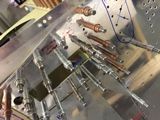
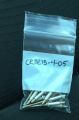
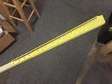
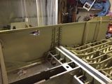
Twisting the upper longeron was a lot easier than I figured it would be. Using a digital level app for my iphone made it a breeze to know when to stop twisting. Another area that I got a little confused was in the lower longeron assembly. When you cut the doublers apart, the plans do show which is left or right, but I didn't want to trust my instinct on that. I decided to ask before riveting if that flange on the doubler points toward or away from the longeron. Van's confirmed that the orientation as above was correct in photo 3. The hole pattern will match up with either part, depending on how it's flipped. Also in this area was where I found that we weren't given an CR3213-4-05 rivets, so they are sending those out to the missed builders now. After that, the longerons were easy to complete and it wasn't long before I had the side skins in place to cut and drill the cowl attach hinge on the firewall. |
|||||||||||||
 |
 |
 |
 |
||||||||||
 |
 |
 |
 |
||||||||||
 |
 |
 |
 |
||||||||||
 |
 |
 |
 |
||||||||||
 |
 |
 |
 |
||||||||||
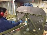
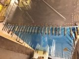
With the longerons done, I was coming up on time to prime the side skins if I wanted to. I decided to do it, because there were areas that would be covered up for good if I didn't do it now. Plus, it's nice to prime at least the rivet lines. In the end, it was easier to not mask everything (except around the air vents) and just prime the entire skin. While I was in a priming mood, I decided to read ahead thru the whole manual and dig through my pile of parts and find out what needed to be cut, trimmed, separated, and dimpled, and see how much of it I could get done. I figured if I primed it all now, it would be done, and give me much less start/stop distraction later. So spending a few hours preparing the parts and a session of spraying and now almost everything is primed. |
|||||||||||||
 |
 |
 |
 |
||||||||||
 |
 |
 |
 |
||||||||||
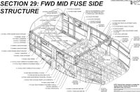
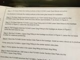
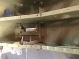
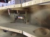
| When you hit page 29-09, you
hit another section where you may cause yourself trouble
if you don't read between the lines. You are to
final drill and machine countersink a few places, and then
dimple the skins. Be careful in that the holes that
are NOT covered by side skins, in the upper longeron, do
not get drilled or countersunk until section 35. If
you do, I think it'll be ok, because they do get it later,
but, you won't have the opportunity to align things and
final drill them to match eachother. The bigger problem is the lower longeron. The plans have you look at figure 1 and not dimple certain areas. The catch is, while they show the F-01485-L center brace in a transparent view, they don't show the lower longeron. 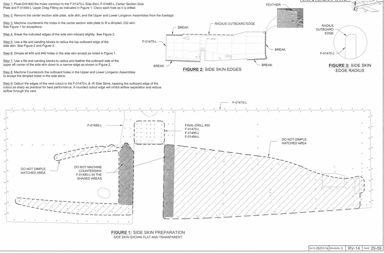 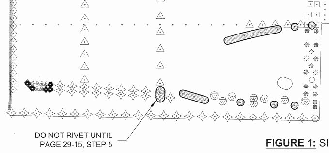 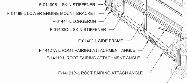 As you can see below, I didn't read between the lines, and ended up with countersunk holes. The fix for me was to just dimple those holes in the skin to match, after thinking about and reading thru the future steps in the plans further. The reason for not dimpling is just because a mushroom head rivet gun will be hard to use in that area. You have overlapping levels of skin/parts, and rivets in close proximity, so it's hard to get the flush rivet set to be flat where you need it. A round head rivet would be easier to put in. Also, those areas are in a non-visible area of the plane when completed so round heads are ok. Basically, I'll have to carefully either rivet with a narrow flat set (like a backrivet set) or I could use CherryMax CR3212 rivets in those places. Either way it'll work out. |
|||||||||||||
 h h |
 |
 |
 |
||||||||||
 |
 |
 |
 |
||||||||||
 |
 |
||||||||||||
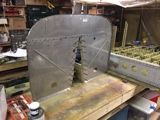
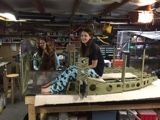
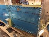
| Once that was figured out, it
was time to rivet a couple of stiffners on to the side
skins, and get them hung in place before I closed up
shop. After a good weekend of progress, it was time
to sit and stew about growing another year uglier. |
|||||||||||||


Previous | Site Home | Next